And closer still
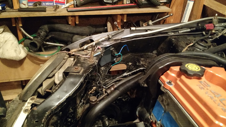
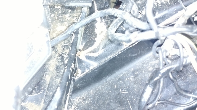
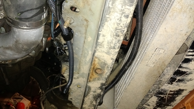
The last couple days have been spent doing small things that make big progress. I’ve got the wiring mostly taken care of. I still need to run the wires to the gauges, but other than that, I think the wiring is good to go. Here’s the view from under the core support for the wires that need to cross the engine bay:
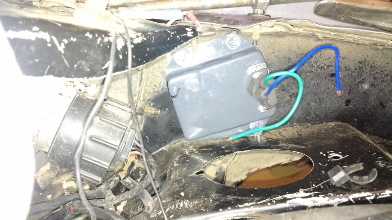
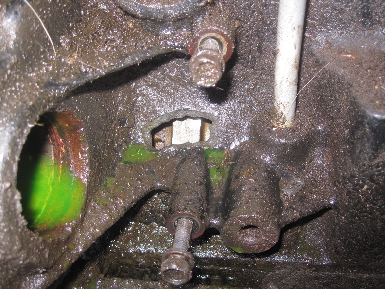
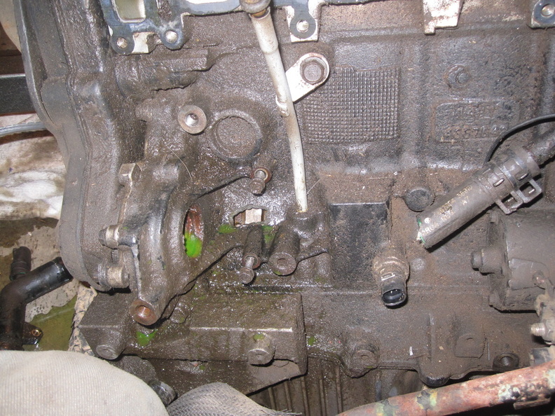
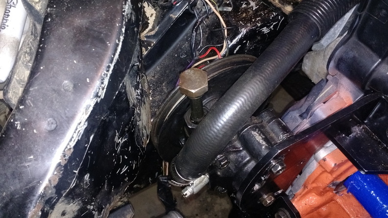
It is going to be critical to have oil pressure readouts, so I needed to repair the oil pressure sender:
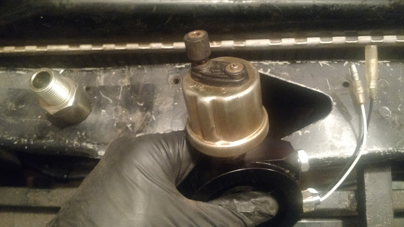
That post snapped off a while back so I tried a couple things to get it repaired. My first attempt was to use a torch and alumaweld to permanently attach a wire to what was left of the stud. That didn’t work, but it did melt the plastic and allow me to pull the stud out, exposing the wire. From there, I soldered on a new wire, covered it with shrink tube, and then used RTV to fill in the hole. It seems pretty solid, so I’m going to give it a try and see if it works.
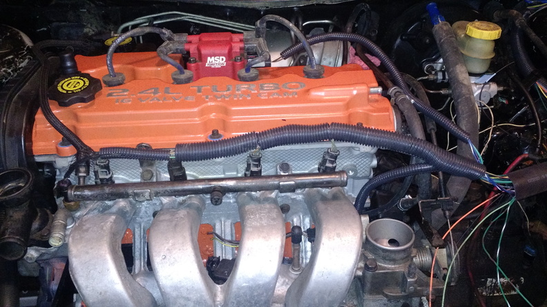
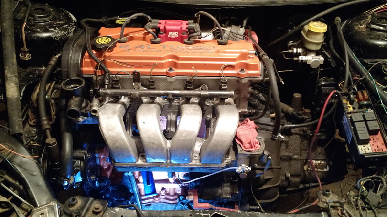
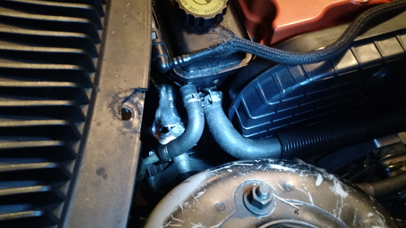
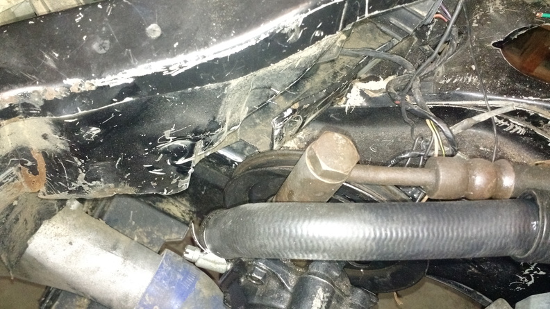
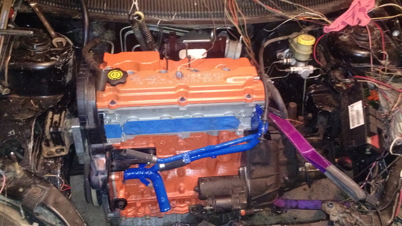
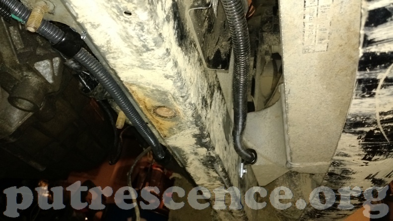
The cooling system is all buttoned up now, with the radiator and fans in place, plus the hose clamps for the heater core lines and the metal strapping in place to support the lower line to the heater core. I also got the high pressure side of the intake all clamped down.
The list:
- PS belt
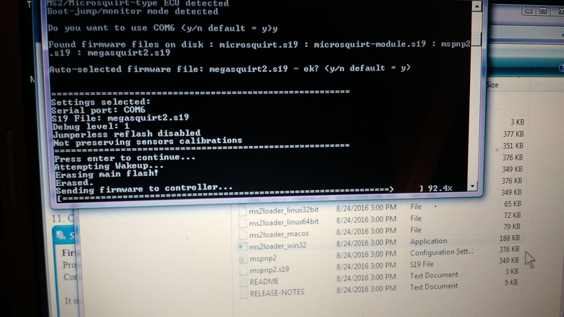
- Re-install MegaSquirt
- Install PCV system
- Run wires for gauges
- Add hose barb to air cleaner pipe for valve cover breather
- Torque down O2 sensor
- Install oil filter sandwich adapter
- Install oil filter
- Fill engine with oil and turn by hand a few times
- Install axles
- Fill transaxle
- Try to start engine
- Re-install front end